Support this open source project, get a Bus Pirate v3 for $30, including worldwide shipping.
Read about the Bus Pirate v3 design.
The Bus Pirate is an open source hacker multi-tool that talks to electronic stuff. It’s got a bunch of features an intrepid hacker might need to prototype their next project. This manual is an effort to link all available Bus Pirate information in one place.
Try the new terminal design preview firmware.
Testers needed for v4 bootloader upgrade and v4 firmware.
Bus Pirate v3 preorder 2 & 3 dead MODE LED fix.
Introduction
- Features overview
- Bus Pirate 101 tutorial
- Bus Pirate 102 tutorial
- Connecting with MAC/OSX
- Bus Pirate forum
- Latest firmware download
Reference
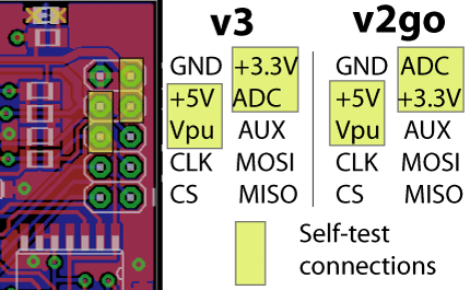
- I/O header pin descriptions
- User contributed pin references
- User terminal mode
- Binary scripting mode
- Bitbang (primary binmode), SPI, I2C, UART, 1-Wire, raw-wire, self-test
- Example scripts in Python, Perl, etc.
- All binmode documentation
Feature guides
- Self-test guide
- Practical guide to Bus Pirate pull-up resistors
- Mixed voltage interfacing with pull-up resistors
- Detect your PIC hardware revision
- UART error flag guide
- I2C software and hardware modes
- I2C address scan
- JTAG
- LCD library and adapter
- HEX/DEC/BIN converter
- HEX/DEC/BIN number entry and output display
- Repeat command
- I2C, SPI sniffers
- Create /dev/bus_pirate on Linux
- Logic analyzer mode
- STK500 v2 AVR programmer clone
- OpenOCD JTAG support
Firmware upgrades
- Bootloader v4:
- v2 to v4 upgrades
- Pirate-Loader console upgrade application (Linux, Mac, Windows)
- ds30 Loader GUI (Mono/.NET)
- Bootloader v2:
- Firmware update guide (Windows)
- Linux, OSX (Python) firmware updates
- OSX detailed upgrade guide
- Faster firmware updates
- Fast upgrades if you have a ‘slow’ PIC chip
Hardware documentation
- USB Bus Pirates: BPv3, v2a & v2go
- Serial port Bus Pirates: v1a, v0a
- SparkFun’s Bus Pirate
- Probe cable
- Bus Pirate v3 preorder 2 & 3 dead MODE LED fix
- 2K ohm MOSI pull-up resistor mod
- Google Code page and SVN repository
- Spanish, Italian translations
- Compile the Bus Pirate firmware
- Modify the FTDI EEPROM, change serial name on OSX
Application guides
Here’s a comprehensive list of Bus Pirate chip demonstrations. It includes Ian’s old demonstrations from Hack a Day, and the most recent demos from Dangerous Prototypes. Tutorials are arranged by Bus Pirate hardware version.
Bus Pirate v2&v3
- 3EEPROM explorer board, DS2431 (1wire), 24AA (I2C), 25AA (SPI)
- Wii Nunchuck quick guide (I2C)
- Nokia 3310 LCD (binary SPI)
- iButton serial number (1-Wire)
- 2AA02E48 EEPROM with MAC address (I2C)
- HD44780 character LCD adapter (LCD)
- DS1307 real time clock (I2C)
- NA204SD02 Futaba VFD character display (raw2wire)
- SLE4442 (FedEx Kinko’s) smart card update (raw2wire)
- 25AA/25LC serial EEPROM (SPI)
- ShiftBrite with A6281 3 channel LED driver (SPI)
- PCF8563 real time clock calendar (I2C)
- Sure LED matrix (raw3wire)
- AT45DB041D 4Mbit flash memory (SPI)
- HMC6352 digital compass (I2C)
- Parallax RFID reader (UART)
- KS0074 serial LCD (SPI)
Bus Pirate v1a
- LTC2640 digital to analog converter (SPI, raw3wire)
- LTC2631A digital to analog converter (I2C)
- PC keyboard (PC Keyboard)
- DS1807 audio volume potentiometer (I2C)
- 23K256 32K serial SRAM memory (SPI)
- SparkFun 4×4 RGB button pad controller (raw3wire)
- DS1801 audio volume potentiometer (SPI)
- MCP6S26 programmable gain amplifier (raw3wire)
Bus Pirate v0a
- 24LC1024 EEPROM (I2C)
- EM406 GPS (UART)
- SLE4442 (FedEx Kinko’s) smart card (raw2 wire)
- DS1077 133MHz programmable oscillator (I2C)
- XC9572XL CPLD (JTAG)
- DS1822 temperature sensor (1-Wire)
- PCF8574 IO Expander (I2C)
- DS2431 1K EEPROM (1-Wire)
- SHT1x/7x humidity and temperature sensor (raw2wire)
- TC74 temperature sensor (I2C)
Reference
This guide explains the Bus Pirate I/O pins, describes each menu available from the Bus Pirate terminal, and documents the syntax functions for each protocol library. This is the master updated copy of the Bus Pirate command reference. Most recently updated for firmware v3.0. See previous guides: v0h, v2.0.
I/O header pin descriptions

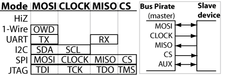
This table displays the Bus Pirate pinout in various modes. The Bus Pirate I/O pins try to be consistent across all libraries, the same pins are used for similar functions. Unused pins are usually in a safe high-impedance state.
Modes not shown in the above diagram are similar to other libraries: MIDI=UART; raw2wire=HD44780=PC keyboard=I2C; raw3wire=SPI. All bus pins output at 3.3volts, but tolerate up to 5volts (5.5volts maximum). Pins are named as they pertain to the Bus Pirate, not necessarily how they connect to the target device. In bus sniffer modes each pin becomes an input for the same signal usually assigned to that pin.
Master-out slave-in (MOSI) is the primary data pin, it’s used for bi-directional data transfer in protocols like I2C and 1-Wire, and as data-out from the Bus Pirate in uni-directional protocols like SPI and asynchronous serial (UART). In bus sniffer modes each pin becomes an input for the same signal usually assigned to that pin.
Clock is always a clock-out signal from the Bus Pirate, except in the PC keyboard library where the keyboard provides a clock signal to the Bus Pirate.
Master-in slave-out (MISO) is used with protocols that have a dedicated data-input, such as SPI and UART.
Chip select (CS) is an output used to activate the serial interface in SPI-like protocols. Use the auxiliary pin config menu (c) to get manual control of the CS pin through the auxiliary pin commands (a, A, @).
The auxiliary pin (AUX) can be used as an output or input from the Bus Pirate terminal interface with the A, a, and @ commands. It’s useful for protocols that require an additional signal, such as a reset.

| Pin name |
Description (Bus Pirate is the master) |
| MOSI | Master data out, slave in (SPI, JTAG), Serial data (1-Wire, I2C, KB), TX* (UART) |
| CLK | Clock signal (I2C, SPI, JTAG, KB) |
| MISO | Master data in, slave out (SPI, JTAG) RX (UART) |
| CS* | Chip select (SPI), TMS (JTAG) |
| AUX | Auxiliary IO, frequency probe, pulse-width modulator |
| ADC | Voltage measurement probe (max 6volts) |
| Vpu | Voltage input for on-board pull-up resistors (0-5volts). |
| +3.3v | +3.3volt switchable power supply |
| +5.0v | +5volt switchable power supply |
| GND | Ground, connect to ground of test circuit |
Notes: * TX moved from CS to MOSI in firmware v0g.
The user interface
Talk to the Bus Pirate from a serial terminal set to 115200bps, 8/N/1.
* Syntax error, type ? for help
HiZ>
Press enter to show the command prompt if your terminal is blank.
HiZ>m <<<set mode command
1. HiZ
…
10. LCD
(1) ><<<press enter to select default option (1)
Mode selected
HiZ>
Most configuration and option prompts have a default value shown in (). Press enter to select the default option.
Read more in the Bus Pirate 101 tutorial.
Menus
| Menu | Description |
| ? | Help menu with latest menu and syntax options. |
| I | Hardware/firmware/microcontroller information (firmware v2.1+). |
| M | Set bus mode (1-Wire, SPI, I2C, JTAG, UART, etc). |
| B | Set PC side serial port speed. |
| O | Data display format (DEC, HEX, BIN, or raw). |
| V | Power supply voltage report (v1+ hardware only). |
| F | Measure frequency on the AUX pin. (1Hz-40MHz) |
| G | Frequency generator/PWM on the AUX pin. (1kHz-4MHz) |
| C | Toggle AUX control between AUX and CS/TMS pins. |
| L | Set LSB/MSB first in applicable modes. |
| P | Pull-up resistors (V0,V2+ hardware). |
| = | Convert HEX/DEC/BIN number format (firmware v2.1+). |
| ~ | Perform a self-test (firmware v2.0+). |
| # | Reset (firmware v2.0+). |
Menu options are single character commands that configure the Bus Pirate. Type a letter, followed by <enter>, to access the menu. Some options are unavailable in some modes and on some hardware.
| Syntax | Description |
| A/a/@ | Toggle auxiliary pin. Capital “A” sets AUX high, small “a” sets to ground. @ sets aux to input (high impedance mode) and reads the pin value. |
| D/d | Measure voltage on the ADC pin (v1+ hardware only). |
| W/w | Capital ‘W’ enables the on-board power supplies. Small ‘w’ disables them. (v1+ hardware only). |
| { or [ | Bus start condition. |
| ] or } | Bus stop condition. |
| R or r | Read one byte. (r:1…255 for bulk reads) |
| 0b | Write this binary value. Format is 0b00000000 for a byte, but partial bytes are also fine: 0b1001. |
| 0h/0x | Write this HEX value. Format is 0h01 or 0×01. Partial bytes are fine: 0xA. A-F can be lower-case or capital letters. |
| 0-255 | Write this decimal value. Any number not preceded by 0x, 0h, or 0b is interpreted as a decimal value. |
| , | Value delimiter. Use a coma or space to separate numbers. Any combination is fine, no delimiter is required between non-number values: {0xa6,0, 0 16 5 0b111 0haF}. |
| & | Delay 1uS. (&:1…255 for multiple delays) |
| (#) | Run macro, (0) for macro list |
| Bitwise | |
| ^ | Send one clock tick. (^:1…255 for multiple clock ticks) |
| / or \ | Toggle clock level high (/) and low (\). Includes clock delay (100uS). |
| – or _ | Toggle data state high (-) and low (_). Includes data setup delay (20uS). |
| ! | Read one bit with clock. |
| . | Read data pin state (no clock). |
A simple syntax is used to interact with chips. Syntax characters have the same general function in each bus mode, such as ‘R’ to read a byte of data.
[ 0x31 r:5]
This example syntax sends a bus start , the value 0x31, and then reads 5 bytes, followed by bus stop. Up to 4000 characters of syntax may be entered into the Bus Pirate terminal at once, press enter to execute the syntax.
I2C>(0)
0.Macro menu
1.7bit address search
2.I2C sniffer
I2C>(1)
Macros perform complex actions, like scanning for I2C addresses, interrogating a smart card, or probing a JTAG chain. Macros are numbers entered inside (). Macro (0) always displays a list of macros available in the current bus mode.
The Bus Pirate always starts in high impedance mode (Hi-Z), a safe mode with all outputs disabled. It’s intended to protect any connected devices from conditions beyond their specifications. Each bus mode is described on the pages below.
Go to: 1-Wire, UART, I2C, SPI, JTAG, raw 2-wire, raw 3-wire, PC keyboard, HD44780 LCDs, MIDI.
—-
The Bus Pirate pinout, menu, and command tables are released into the public domain. Based on the public domain Bus Pirate documentation at Hack a Day.
